Streamlined Kafka Schema Evolution in AWS using MSK and the Glue Schema Registry
In today’s data-driven world, effective data management is crucial for organizations aiming to make well-informed, data-driven decisions. As the importance of data continues to grow, so does the significance of robust data management practices. This includes the processes of ingesting, storing, organizing, and maintaining the data generated and collected by an organization.
Within the realm of data management, schema evolution stands out as one of the most critical aspects. Businesses evolve over time, leading to changes in data and, consequently, changes in corresponding schemas. Even though a schema may be initially defined for your data, evolving business requirements inevitably demand schema modifications.
Yet, modifying data structures is no straightforward task, especially when dealing with distributed systems and teams. It’s essential that downstream consumers of the data can seamlessly adapt to new schemas. Coordinating these changes becomes a critical challenge to minimize downtime and prevent production issues. Neglecting robust data management and schema evolution strategies can result in service disruptions, breaking data pipelines, and incurring significant future costs.
In the context of Apache Kafka, schema evolution is managed through a schema registry. As producers share data with consumers via Kafka, the schema is stored in this registry. The Schema Registry enhances the reliability, flexibility, and scalability of systems and applications by providing a standardized approach to manage and validate schemas used by both producers and consumers.
This blog post will walk you through the steps of utilizing Amazon MSK in combination with AWS Glue Schema Registry and Terraform to build a cross-account streaming pipeline for Kafka, complete with built-in schema evolution. This approach provides a comprehensive solution to address your dynamic and evolving data requirements.
Architecture
I would like to start by introducing the infrastructure that we are going to deploy as part of this blog post. The architecture diagram below provides a high-level snapshot of the components and workflow we are about to implement. Our objective is to build a cross-account streaming pipeline using AWS MSK and AWS VPC Endpoint Services.
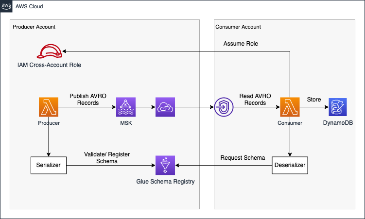
The Producer Account houses the Amazon MSK Kafka Cluster and Kafka Lambda producers. To make our cluster available to the Consumer Account, we’ll create a VPC Endpoint Service using Network Load Balancers and AWS Private Link. Leveraging Private Link allows us to expose our Kafka cluster as an internal AWS network service. In our simulated real-time workflow, event streaming data is created by Lambdas in the Producer Account and writing to a Kafka topic in the AVRO format. AVRO stores data definitions in JSON format alongside the data. This ensures easy readability and interpretation, with the actual data stored in a compact and efficient binary format.
In addition to the MSK cluster, we integrate the Glue Schema Registry into our workflow for schema evolution. The Lambda producers expect the payload as an event input and validate as well as register data schemas into the Schema Registry each time a message is written to a Kafka topic. The producer is configured to dynamically analyze the event data structure and register its schema during runtime. This means that the schema is derived dynamically from the input event, eliminating the need to define a JSON schema beforehand.
Beyond the Schema Registry, the Producer Account provides a cross-account IAM role, offering access to predefined parts of the Glue Schema Registry. This role can be assumed by entities needing schema access, enabling centralized schema management and permission control for consumers within the producer account.
Moving forward, once the Producer Account is established, we shift focus to the Consumer Account. Connecting to the VPC Endpoint Service of the Producer Account via VPC Endpoints ensures secure access to the Kafka Cluster from within the Consumer Account. To resolve Kafka broker domains, we create a Private Hosted Zone with records mapping Kafka broker domains to VPC Endpoint IPs. Subsequently, we set up AWS Lambda functions as Kafka consumers, utilizing Lambda Event Source Mapping for self-managed Kafka to reliably trigger functions whenever an event is written to the Kafka cluster by the producers.
Upon being triggered and receiving an AVRO payload, the Lambda assumes the cross-account IAM role in the producer account. Leveraging the assumed permissions, it requests the appropriate schema from the Glue Schema Registry. Once the schema is obtained, the consumer utilizes the information to deserialize the binary data, making it readable, and subsequently stores the deserialized payload into a DynamoDB table.
The architecture diagram below provides a more detailed overview of the system.
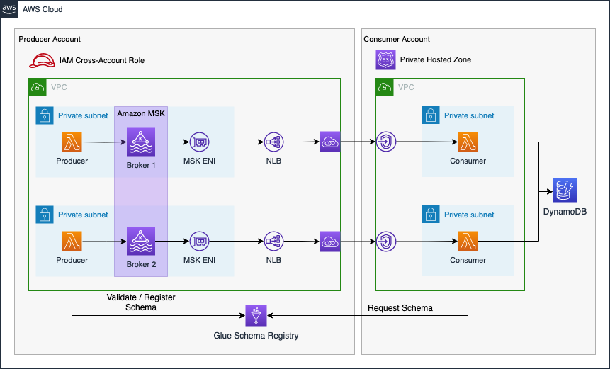
The connectivity pattern used for this example was highly inspired by the official AWS Big Data Blog Post Secure connectivity patterns to access Amazon MSK across AWS Regions. Please visit the original post to get a better understanding of the pattern employed and possible alternatives.
This blog post will not delve into details regarding Kafka, AVRO, or schema evolution concepts in general. It is advisable to have a basic understanding of these concepts to fully grasp the architecture and workflow presented in the blog post.
Bootstrap Environment
The code associated with this blog post is hosted on GitHub. You are welcome to either clone the repository or manually copy the code to your local machine. In the provided directory, you will discover two distinct folders. The producer folder encapsulates the entire Terraform configuration for the Producer Account, including MSK cluster, Glue Schema Registry, IAM role, and VPNC Endpoint Service. The consumer folder contains the entire Terraform configuration for the Consumer Account.
Prior to deploying our infrastructure, certain adjustments must be made to our Terraform provider configuration. Open the provider.tf file, where you will encounter the following provider blocks. Please establish an AWS profile for each provider. Alternatively, employ different methods to supply credentials to the provider blocks. A comprehensive overview of the available attributes can be found in the official documentation.
################################################################################
# Set required providers
################################################################################

provider "aws" {
  alias = "producer"

  profile = "xxxxxxxxxxx"

}

provider "aws" {
  alias = "consumer"

  profile = "xxxxxxxxxxx"
}
In this example, we employ two separate AWS accounts. However, if you prefer not to utilize distinct AWS accounts, feel free to use identical account details for both provider blocks. This approach will deploy the entire infrastructure into the same AWS account.
After making the necessary adjustments, the next steps involve building both the producer and consumer applications, both written in Java. Both applications need to be packaged into a JAR file, which will be uploaded to an S3 Bucket during the infrastructure deployment process. Navigate to the folders producer/code as well as consumer/code and run the command mvn package in order to create a JAR file of both applications.
Once this is done, execute terraform init to initialize the Terraform providers, and then use terraform apply to deploy the infrastructure. After the successful deployment of the entire infrastructure, we will delve into an in-depth examination of our producer and consumer applications. Additionally, we will explore how schema evolution can be supported using the Glue Schema Registry.
Please be aware that deploying an MSK cluster in AWS can take up to 40min. Make sure to allocate enough time before starting this example.
Schema Evolution Demo
Navigate Environment
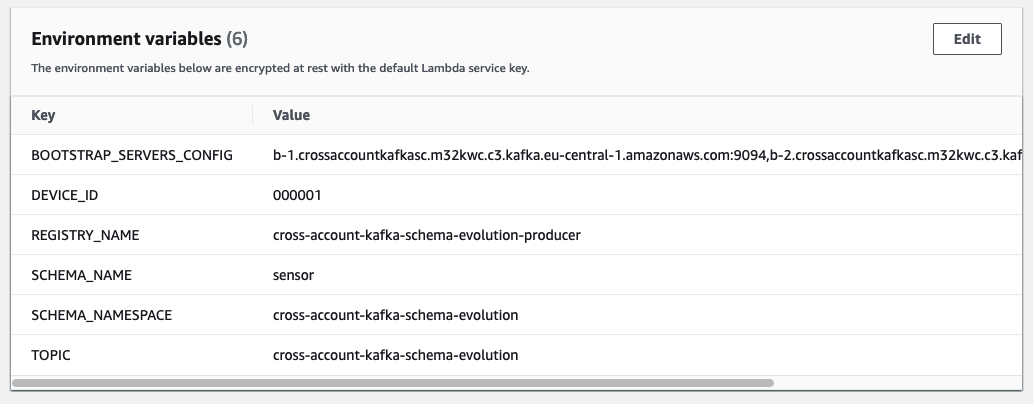
After a successful deployment, begin by exploring the AWS Console for both Accounts. First, log in to the Producer Account and navigate to the Lambda console, where you’ll find our producer Lambda.

Take the opportunity to explore the function and its configuration. Later in this demo, we will use this function to generate payloads for our consumer. Specifically, in this demo, the producer Lambda functions as an IoT sensor identified with the Device ID 000001.
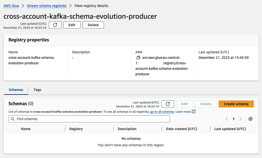
Next, move to the Glue Console to examine our freshly deployed Schema Registry. While keeping the Lambda console open, open a new tab, and access the Glue Console to navigate to the Glue Schema Registry.

This Schema Registry will house our schema and all the schema versions created dynamically as part of this demo. Upon opening the Registry, you’ll observe that there are currently no schemas present. We’ll create our schema and versions dynamically in the course of this demo.
After exploring the Producer Account, switch to the Consumer Account.
If a second AWS Account is used during this demo, it is advisable to either use a different browser or a container plugin to be logged into both accounts simultaneously.
Open the Lambda Console in the Consumer Account, where you’ll find the consumer Lambda functions. Feel free to explore the function and its configuration. This function has a preconfigured trigger that triggers the Lambda function each time a new message is written to the Kafka cluster. It processes the payload and stores the result in a DynamoDB table.

Open a new tab and navigate to the DynamoDB console, where you’ll find our empty DynamoDB table. As soon as we start publishing messages to our Kafka cluster, you’ll see the DynamoDB table filling up.
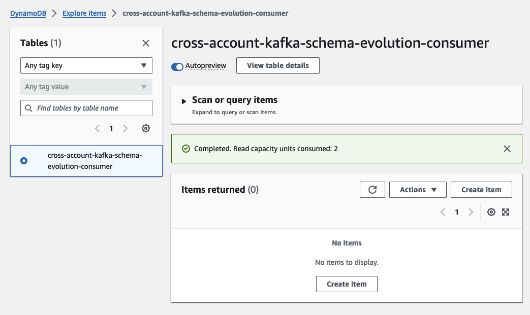
Empty Test Event
We’ll initiate the process by sending an empty test event using the producer Lambda. This action will create our initial schema version in the registry and store the first payload in the DynamoDB table. To begin, access the producer Lambda, and navigate to the Test tab. Under Test Event, choose the option Create New Event. Name the new event EmptyTestEvent. The payload for this event should be an empty JSON construct.
{}
Save the new test event. You should see the following test event.
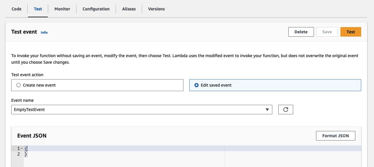
Click on Test to trigger the producer Lambda with the newly created test event. The Lambda function will run for a few seconds before completing successfully. During this process, the Lambda publishes a message to the Kafka topic. As the topic did not exist previously, the function also created it as part of the Kafka initialization process. Additionally, it registered a new schema and the first schema version in our Schema Registry. Navigate to the Glue Console to witness the creation of the new schema.
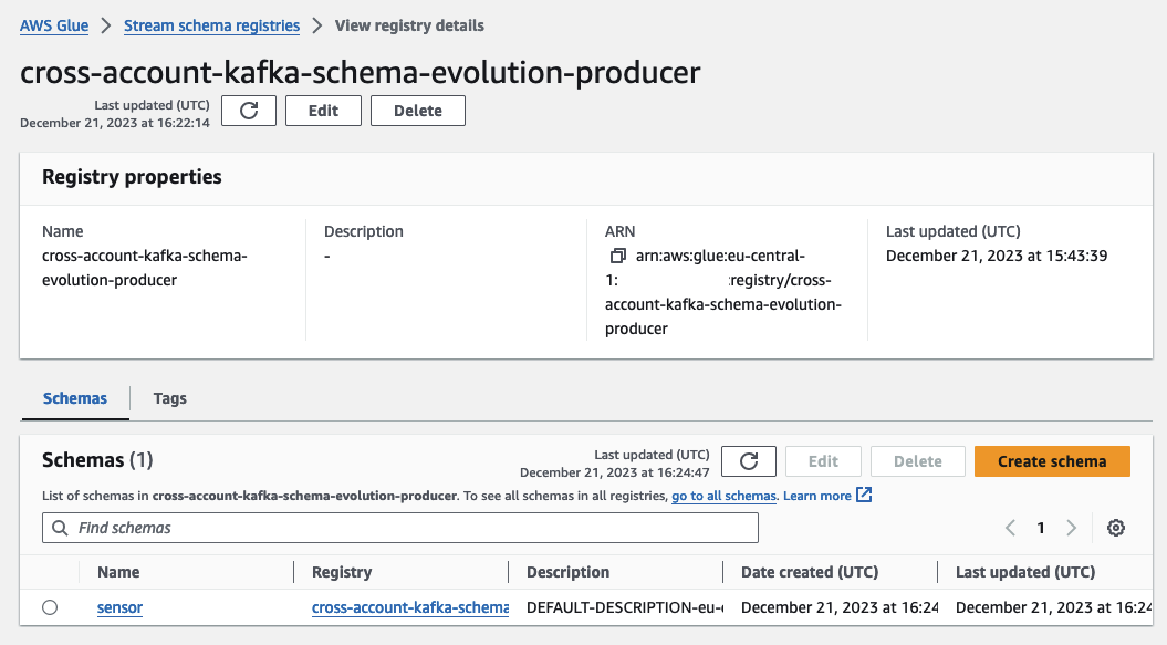
Open the sensor schema, where you’ll find the first schema version. Feel free to explore both the Schema Registry and the newly created schema to gain a comprehensive overview.
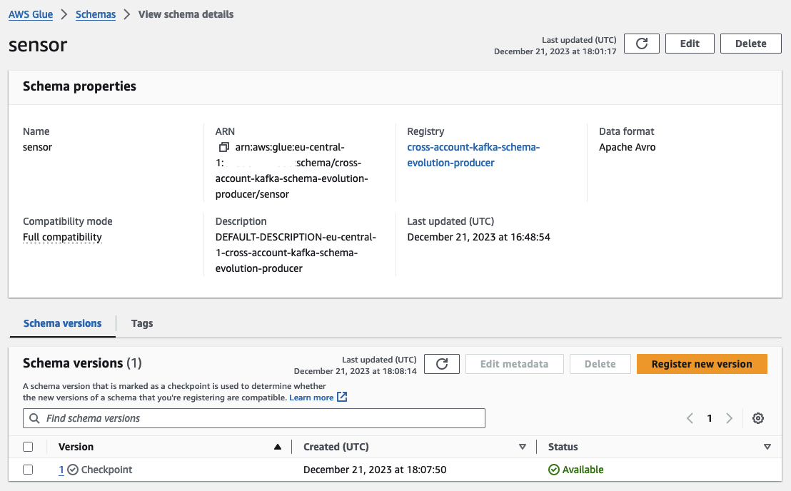
Having explored the producer side, let’s switch to the Consumer Account. Reopen the DynamoDB Console to observe the newly added entry. Since our test event comprised only an empty JSON, the producer message contained only the deviceId and a timestamp. To illustrate schema evolution, we will now utilize this base schema to add additional fields and values to our simulated IoT sensor.

Add Temperature
After sending an empty test event to initiate the process, we will enhance the schema of our simulated IoT sensor by introducing a new field that displays the sensed temperature. Navigate to the producer Lambda and create another test event. Open the Test tab, and under Test Event, select the option Create New Event. Name the new event AddTemperatureEvent. The payload for this event should be a JSON construct containing a temperature value.
{
  "temperature": 30
}
Save the new test event. You should see the following test event.
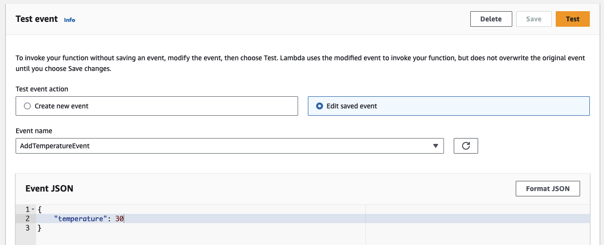
Initiate the producer Lambda by clicking on Test. The Lambda function will execute for a brief period before completing successfully. During this phase, the Lambda publishes a new message with a distinct schema to the Kafka topic and registers the new schema version in the Glue Schema Registry. This schema is dynamically determined and registered at runtime. Head to the Glue Console to witness the creation of the new schema version.

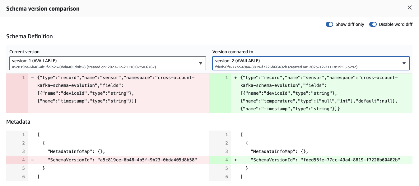
We now have two schema versions, and the disparity between them becomes evident when utilizing the built-in Compare function of the Glue Schema Registry. Click on schema version 2, select Compare with a different version, and choose both version 1 in the left box and version 2 in the right box. The comparison reveals the automatic addition of a new field, temperature, to the schema.
Having explored the producer side, let’s switch to the Consumer Account. Reopen the DynamoDB Console to find the newly added entry, now displaying the temperature alongside the deviceId and the timestamp.

Fantastic! We’ve achieved a seamless schema evolution of our initial schema by effortlessly incorporating a new field. Notably, there was no need for any adjustments to either the producer or the consumer application. Everything continued to function flawlessly, all thanks to the robust support provided by the Schema Registry and the efficiency of the data serialization and deserialization processes.
Remove Temperature
Having introduced the temperature field to our payload and schema, let’s now observe how our pipelines respond when we attempt to remove this field. Head to the producer Lambda, navigate to the Test tab, and instead of creating a new test event, select the previously generated EmptyTestEvent. The JSON for this event will now be an empty construct, no longer containing the temperature field and value.

Trigger the Lambda function using the EmptyTestEvent, and once the function completes successfully, open the Glue Schema Registry. You’ll notice that no new schema version has been added to the registry. We still have our two previous schema versions—one with and the other without the temperature field. This is logical since the message we just sent utilized a schema that already existed and did not introduce new fields.

Now, let’s switch back to the Consumer Account, open the DynamoDB Console, and you’ll find the newly added entry displaying only the deviceId and the timestamp.
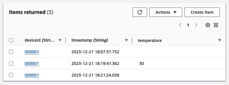
As demonstrated, we’ve successfully removed a field from our producer message without impacting the behavior or performance of our pipelines. Both the producer and the consumer adeptly handled messages that were missing fields from the previous schema version without any issues.
Summary
Congratulations! You have successfully implemented a cross-account Kafka streaming pipeline, complete with schema evolution. While this infrastructure serves as a foundational example, it underscores the power and flexibility of employing schema evolution in general, along with the possibilities that arise when integrating MSK with the Glue Schema Registry.
As emphasized at the beginning, schema evolution is a crucial concept for every data-driven company. It enables you to swiftly adapt to changing business requirements without jeopardizing the uptime and performance of your production environment. This blog post is designed to demonstrate how you can leverage AWS services and Terraform to efficiently implement and incorporate these concepts into your workflow.
I hope you had fun and learned something new while working through this example. I am looking forward to your feedback and questions. If you want to take a look at the complete example code please visit my Github.
— Hendrik
Title Photo by Chris Lawton on Unsplash
